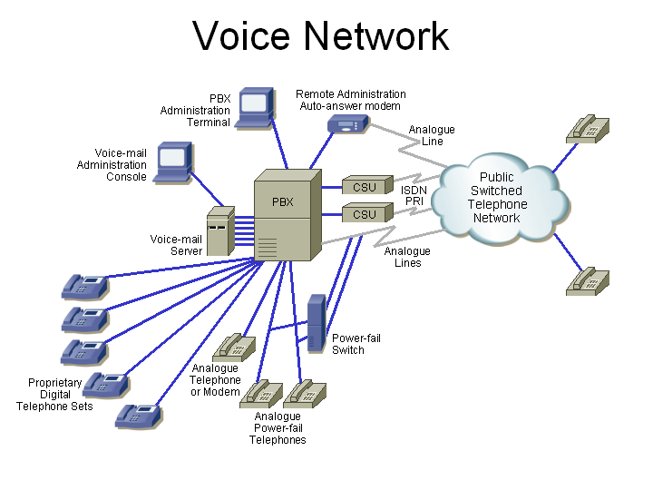
Let's talk about voice networks. Here is a typical traditional (that is, no Voice over IP) voice network. It includes the following:
Here is an overview of the components:
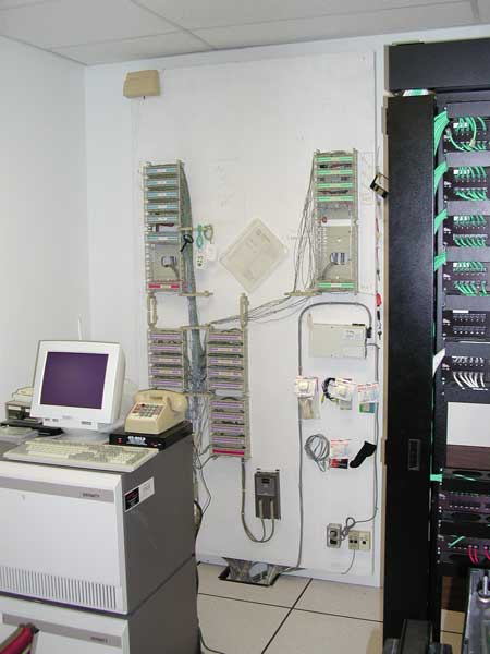
Let's look at this in detail ...
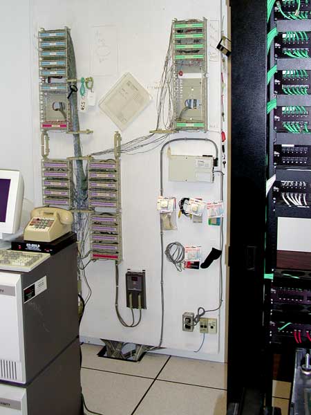
Continuing from the first pictures (which were here), here is the punch-down block connected to the copper pairs from the telephone company. The two white cables going down at the right are the T1s. Some of the yellow and blue pairs at the lower left are the analogue trunks going to the PBX.
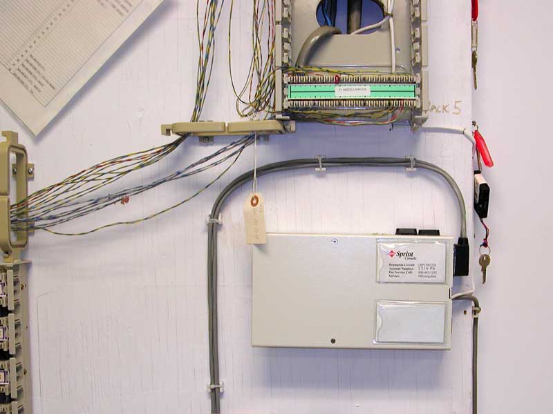
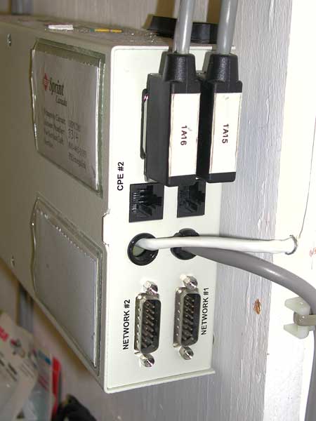
In this enclosure (with the Sprint label which shows the circuit numbers and the telephone number for service) are the HDSL line extenders for the two voice T1 lines. The line extenders are required since the length of the cable to the Central Office is too great for a standard T1 circuit. Some information on these PairGain HRU-402 HDSL Remote Units is here. The line extenders are powered through the thicker cable going down the wall on the right, the HDSL lines from the CO are in the white cable in the middle, and the T1 lines to the PBX are the two grey cables terminated on the black DB-15 connectors which are plugged into the enclosure at the top-right.
A T1 circuit multiplexes 24 64-kbit/s full-duplex (simultaneous send and receive) channels into a 1.544 Mbit/s communication circuit. A T1 requires two pairs. One pair is used to transmit, and the other is used for receive. In this case, the white cable has four pairs, and is carrying two T1s which are here used for voice traffic.
The T1s are each used to carry an ISDN (Integrated Services Digital Network) PRI (Primary Rate ISDN) circuit (sometimes called Primary Rate Access – PRA). ISDN requires a 64 kbit/s D (Delta) channel to carry the on-hook/off-hook, dialled telephone number, caller ID and other line supervision information, leaving the other 23 channels on that PRI available to carry voice conversations. Because there are two PRIs going to the same PBX (Private Branch Exchange – the company's telephone switch), the one D channel can be shared for both PRIs, so all 24 channels of the second PRI are used for voice. Therefore, the two PRIs carry 47 digitized voice conversations plus line supervision.
T1s to the customer equipment (such as a PBX) typically use either a DB-15 or RJ-45 connector. In this case, the enclosure houses two CSUs, which each provide both connectors. Here, the DB-15 connectors are used and the RJ-45 connectors are left open.
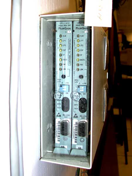
Here's the front of the CSU enclosure, showing the two CSUs.
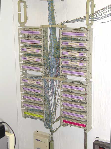
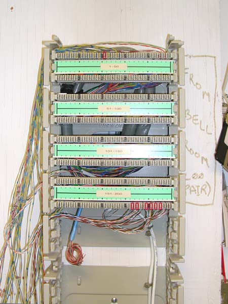
Both PRI trunks (Bell Canada calls these Megalink circuits) and the analogue trunks (Bell Canada calls these 1FL circuits) go to this punch-down. 25-pair cables punched-down to the back of the BIX wafers go through holes in the backboard, down below the raised computer-room floor, and up to the back of the PBX. We'll see that soon, but first, the front of the PBX.
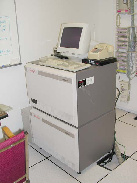
Here is the front of the PBX. It connects to trunks to the telephone company, and provides telephone lines to the users. There are three types of telephone lines:
PBXs connect to two types of trunks:
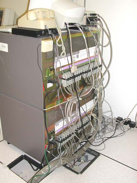
Here's the back of the Avaya (formerly Lucent – and AT&T before that) Definity PBX. The analogue and digital (ISDN PRI) trunks come up through the floor (from the punch-downs on the backboard) to RJ-21 connectors (which each connect 25 pairs) on the back of the PBX. The other RJ-21s carry the telephone line pairs from the PBX to the cross-patch panel, and from there to everybody's telephone sets. Other cables connect to the:
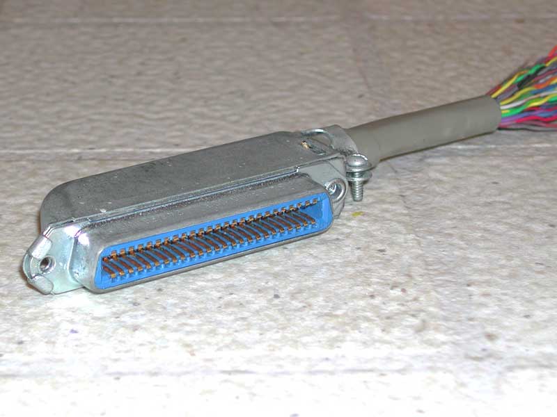
Here is an RJ-21 connector. It has 50 electrical contacts. Pin 1 is at the bottom-left, and pin 26 is at the top-left. These two contacts connect to the two wires of a twisted pair, such as the blue/white for pair 1. Pair 2 connects to the next two pins (2 and 27), and so on.
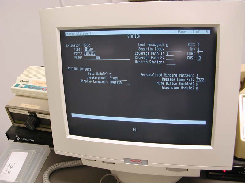
Here's the administration terminal for the PBX, in one of the 5 pages
for the cha sta 3722 function. This changes the station settings for
telephone extension 3722, and illustrates that with training, the user
interface is very functional (and the commands not so cryptic). But many users
want graphical user interfaces with pull-down menus and check-boxes so
less-frequent users of the system can still figure out how to accomplish
tasks.
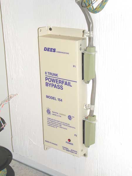
Here is the power-fail bypass that connects the eight outside analogue lines directly to the power-fail telephone sets if the PBX fails (typically because of a power failure).
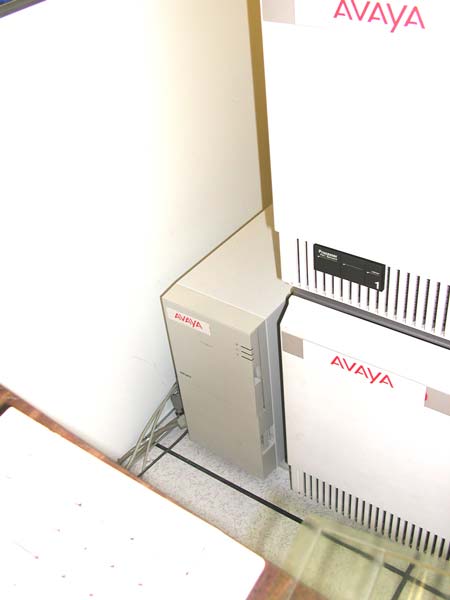
Beside the PBX is the voice-mail system. This is a PC with high capacity hard disk (to store the prompts, greetings, and people's messages), tape drive (to back-up the data and digitized voice files), and 12 channels of audio lines (which can generate digitized speech, digitize incoming speech, detect DTMF tones, and perform a switch-hook flash to transfer calls, for example). The PBX is programmed to:
That is, a voice-mail system is connected to a PBX through lines, just as normal telephone extensions are. Programming on the PBX is what ties it all together.
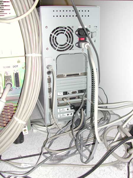
Here's the back of the voice-mail system. The 12 voice lines from the PBX are in the grey cable going to the black connector.
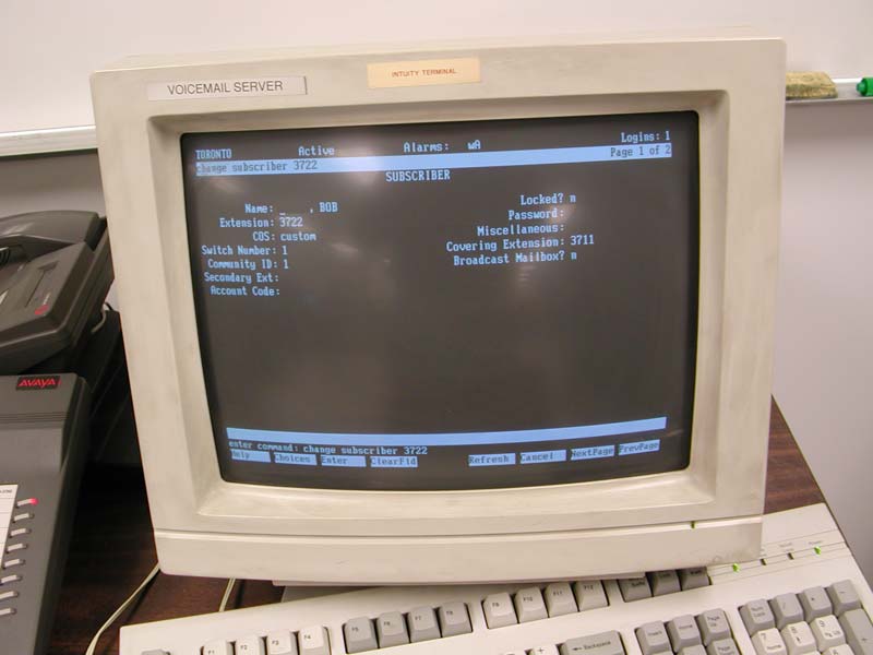
The voice-mail system has a PC monitor and keyboard, just like any Personal Computer does. In this case, these are used to administer the voice-mail system. Here is a typical screen.
To summarize, we have the T1 pairs coming in from the service entrance to the back of the punch-downs at the top-right. The T1 pairs go down to the CSU (the box below those punch-down), to the punch-down at the lower-left, and from there to the PBX. The telephone line extensions from the PBX go from the RJ-21 connectors on the back of the PBX, back to the punch-downs at the lower-left, and then to the back of a field of RJ-45 connectors, as shown in the next photograph.
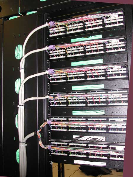
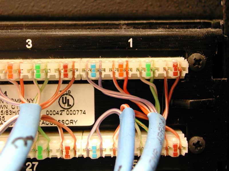
These panels have 48 RJ-45 connectors per section, fed by a 50-pair cable. The last pair from each 25-pair binder group (wrapped with a coloured thread) is not used, so you see the voilet/slate (purple/grey to you and me) pairs wrapped around the end of the jacket).
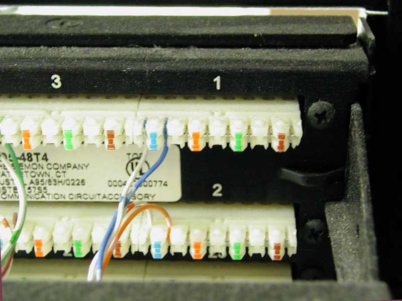
An RJ-45 connector has eight electrical connections (as required for four pairs), but for voice telephone, only one pair is used. Here you can see just one of the 25 pairs punched-down to each of the RJ-45 receptacles (only to pair 1, which goes to the centre two pins of the RJ-45, which is normally the blue/white pair – pairs 2, 3, and 4 are orange/white, green/white, and brown/white, as you can see).
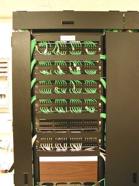
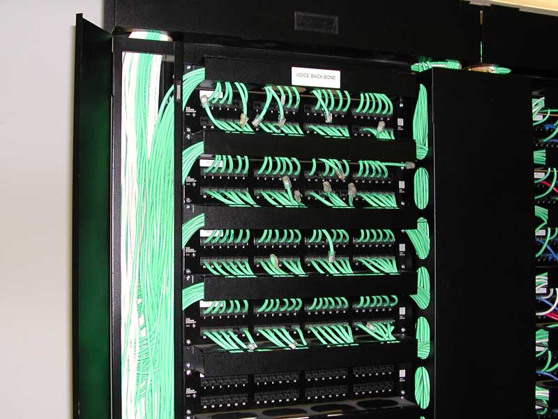
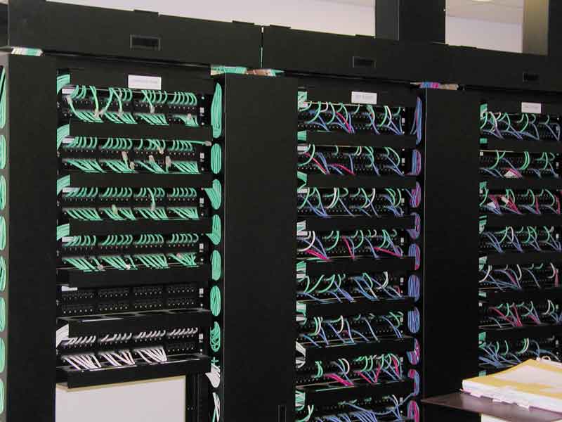
Here is the front of the rows of RJ-45 connectors (which each going to a PBX telephone line). This very organized installation uses green cables for digital telephone sets, and white for analogue telephone sets (at the bottom). This patch cable bay is the far left bay in the photograph below.
The cables are routed behind magnetically-latched doors. Here the left vertical door is open so you can see the huge bundle of cables going down below the floor, to the two bays to the right.
Here's what an RJ-45 panel looks like with no cables plugged in.
The green cables from the left bay (from the PBX) go to the next two bays – which go to the office RJ-45 receptacles. The white cables connect analogue PBX ports to facsimile machines, modems and power-fail telephones in the offices. The blue cables connect the Ethernet switches (the LAN) to PCs in the offices (and servers in the computer room). Finally, the red cables connect the IBM AS/400 minicomputerterminals (called 5250 terminals)
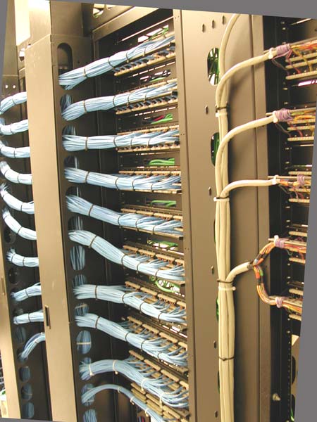
So here we are, behind the cross-patch panel again. The grey PBX cables are at the right, and the bay on the left has blue 4-pair cables that go to the RJ-45 receptacles in each office (actually, this installation has four RJ-45 jacks per office, most installations have two RJ-45s per office, intended as one for voice, and one for data).
Note that all four pairs of these cables are punched down, so they can be used for voice (which usually only needs one pair per telephone) or data (which needs two pairs for 10 Mbit/s or 100 Mbits/s Ethernet, and four pairs for gigabit Ethernet).
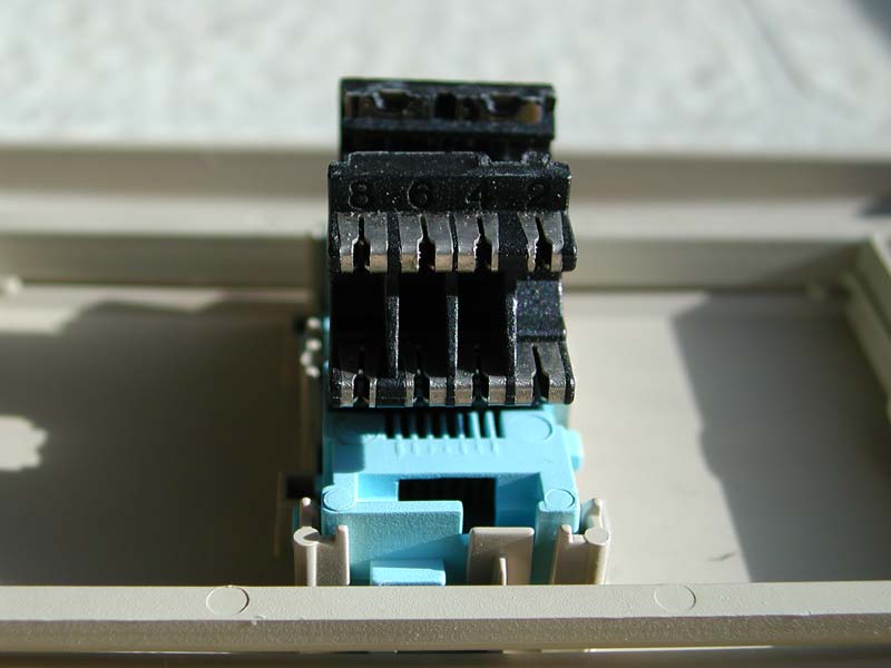
The UTP cabling runs from the back of the cross-patch panel, above the ceiling, to the destination office, down the inside of the wall, and to the RJ-45 wall receptacle. Since this cabling starts and ends on the same floor of a building it is also called horizontal cabling. Here is the back of the wall receptacle, showing the insulation displacement connectors into which the conductors get jammed by a punch-down tool.
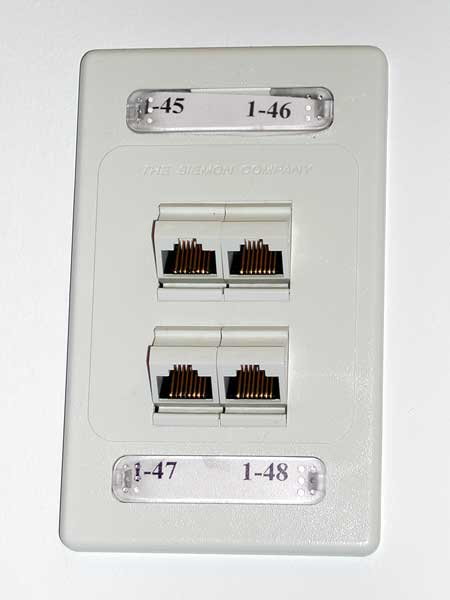
Here's the front of the wall receptacle as you'd usually see it. The RJ-45 patch cord plugs into here, and then into your telephone.
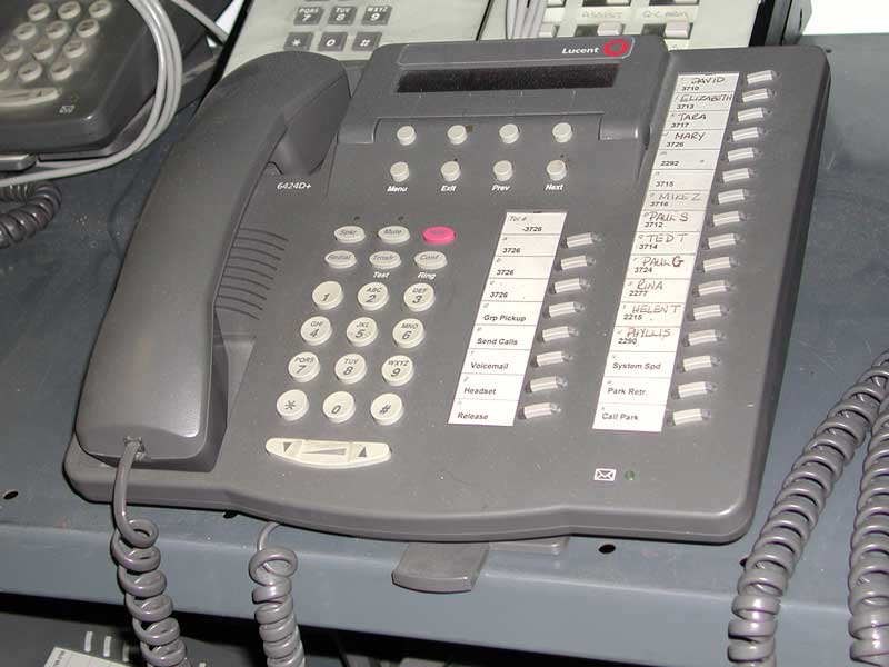
Finally, something we all recognize – a standard digital telephone set. Note the feature buttons below the LCD display, which are labelled according to the text on the LCD display. Unlike your basic home telephone, these telephones require power, which is provided from the PBX, though the same pair of wires that the voice uses.
So there you have it, pictures of the actual boxes, cables, and connectors for the above voice network.